


Document Actions
gvSIG-Desktop 1.10. User Manual
Coordinate Reference Systems
The jCRS extension intends to bring rigorous CRS handling capacity to gvSIG, as well as the incorporation of the standard CRS operations and repositories like, in this version: EPSG, ESRI, IAU2000 and user-defined CRS.
These added functions provide a solution to the ED50-ETRS89 transition problem, and in accordance with the implementation of the Royal Decree 1071/2007, two solutions are integrated that were achieved by the National Geographic Institute (IGN):
- Through the EPSG, the different official IGN achievements are incorporated following the seven-parameter transformation model.
- Through Proj4, the official IGN grid based transformations with grid files in NTv2 format are incorporated.
Further in this document, the user interface for this extension will be described, using the most common cases.
In the description of these cases, there might be an overlap in CRS selection methods and dialogs. To avoid repetitions, it was considered convenient to explain a dialog in detail the first time that it appears in the manual, and therefore users are advised to read the sections in the correct order.
In this latest version of the jCRS extension, users can define a custom CRS. This functionality is available through the CRS selection dialog, see figure 14.
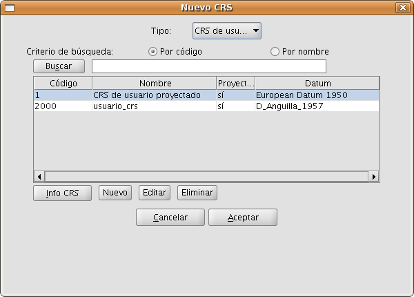
Figure 14: Selection of a user-defined CRS
When selecting User CRS as the type of CRS, you can choose from the following options:
- Choose a custom CRS that was previously defined, by selecting it from the table and click on OK. To facilitate the selection when there are many user-defined CRS, there are two search options to find common CRS: by code and by name.
- To find information on the selected CRS, you can click on the CRS info button, after which a window with the available information will appear.
- To edit the selected CRS, click on the Edit button. A dialog with different tabs will appear which is similar to the dialog in which you can define a new custom CRS. These dialogs will be described later on in this document.
- To delete the selected CRS, click on the Remove button.
- Create a new custom CRS, as described here below.
To create a new custom CRS, click on the New button in the dialog shown in Figure 14, after which the dialog User defined CRS will open (see figure 15) to guide you through the process of creating a custom CRS.
This dialog includes three tabs:
- User CRS, where you can choose between three alternatives to create the CRS:
- From user definitions. With this option, the user will enter all the needed information to create the CRS. When this option is selected, the panels in the Datum and Coordinate system tabs will appear empty so that the user can fill them, although some information (ellipsoid, prime meridian, …) can be taken from other CRS that are included in EPSG.
- From an existing CRS. This option permits the selection of an existing CRS from EPSG, by clicking on the button with three points, load the information in the corresponding panels under the Datum and Coordinate system tabs, and create the custom CRS by modifying this information.
- From a WKT string. This option is similar to the previous one, but here the WKT string is used to load the information of an existing CRS in the corresponding panels of the Datum and Coordinate system tabs.
- Datum, where you can enter the Datum information associated with the CRS.
- Coordinate system, where the information of the coordinate system associated with the CRS is filled.
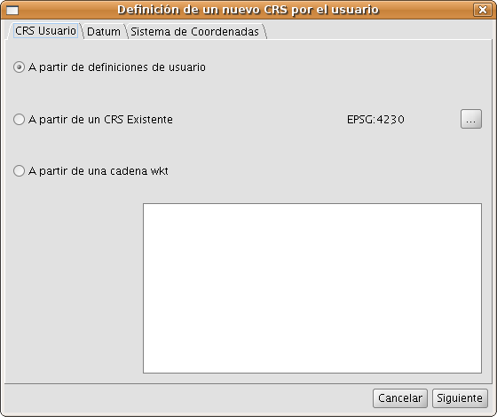
Figure 15: Create a new custom CRS
By clicking the button Next you can move from one tab to the next.
In figure 16, the panel of the Datum tab is shown. In this tab, the following information must be filled:
- Information about the CRS to be defined that will be used in search queries:
- Name. Alphanumeric string to indicate the name of the CRS.
- Code. Integer number to be assigned to the CRS for indexing in the database, this must be a unique number that has not been previously assigned to another custom CRS.
- Information about the datum associated with the CRS:
- Name of the datum. Alphanumeric string to indicate the name of the datum. This can be selected from an existing EPSG CRS by clicking on the button with three points on the right of the text box.
- Ellipsoid. Information on the reference surface of the CRS to be defined. This can be selected from an existing EPSG CRS by clicking on the button with three points on the right of the text box for the ellipsoid name. The information to be filled is:
- Name of the Ellipsoid. Alphanumeric string to indicate the name of the ellipsoid.
- Shape and dimensions of the ellipsoid. You can choose between two options:
- a, inv_f, which refers to the semi-major axis and inverse flattening. To define the semi-major axis correctly it is necessary to enter the value and corresponding unit.
- a, b, which refers to the semi-major and semi-minor axis of the ellipsoid. This option should be chosen when the reference surface is a sphere, in which case the values of both semi-axes are equal and the resulting value of the inverse flattening is infinite. To define correctly both semi-axes of the ellipsoid, the value and corresponding unit must be entered.
- Meridian. Here, the name of the prime meridian that is used for the datum must be filled. You can select the prime meridian from an existing EPSG CRS by clicking on the button with three points on the right of the textbox for the meridian name. The following information must be filled:
- Name of the meridian. Alphanumeric string to indicate the prime meridian.
- Longitude. Geographic longitude relative to Greenwich. The value and corresponding unit must be filled.
The default ellipsoid and meridian for user defined CRS are the GRS80 ellipsoid and Greenwich meridian.
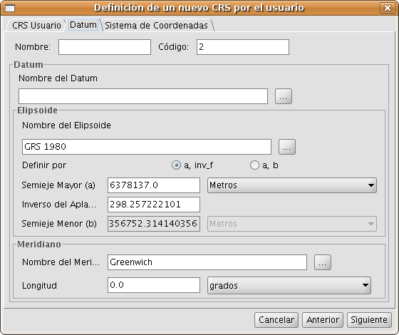
Figure 16: Definition of the datum for the CRS
When the datum parameters are defined, the Coordinate system information associated with the CRS must be filled in the next tab as shown in figure 17.
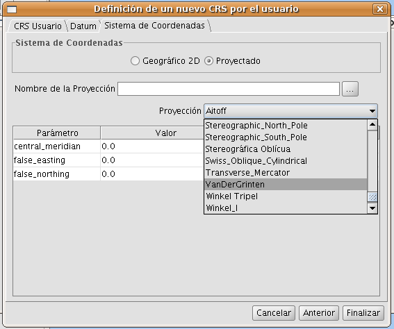
Figure 17: Selection of the coordinate system for the CRS
The following Coordinate system information must be filled:
- Coordinate system: Geographic 2D or Projected.
- In case of a projected coordinate system, the following must be filled:
- Name of the projection. Alphanumeric string to indicate the name of the projection.
- Projection. One of the available options of the drop-down list must be chosen.
- Projection parameters: Value and unit. The list of parameters will change according to the type of cartographic projection.
To edit a custom CRS that was previously defined (see figure 14), select this CRS from the table and click on Edit.
Below in figure 18 the dialog Definition of a new custom CRS is displayed, where the tab User CRS is disabled as well as the CRS code in the Datum tab. The reason why you can not modify the CRS code is that this code is used for the indexation of the user database. The other values for the datum are editable, as well as the values for the Coordinate system tab (see figure 19).
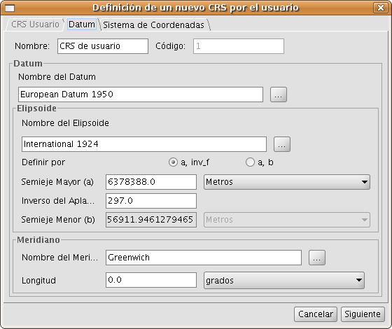
Figure 18: Editing of the datum values
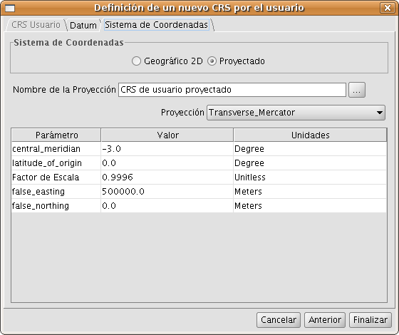
Figure 19: Editing of the coordinate system of the CRS
The selection of the CRS for a layer can be done by adding the layer to a view, and clicking on the button labelled Current projection in the Add layer dialog (see figure 12).
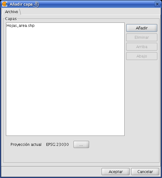
Figure 12: Add layer
Then the dialog CRS and transformation will open where you can select the CRS for the layer, and, if needed, a transformation to load the layer into the view (see figure 13).

Figure 13: Selection of the CRS for a layer
Compared to the New CRS dialog that was described before, what is new here is that the table of used CRS includes a Transformation column. This column facilitates the simultaneous selection of the CRS and the transformation for a layer, but only if these have been used before.
The selection of a transformation will be described hereafter.
The CRS for the View must be defined through the dialog View properties which can be accessed by clicking on the Properties button in the Project manager of gvSIG (see figure 9).
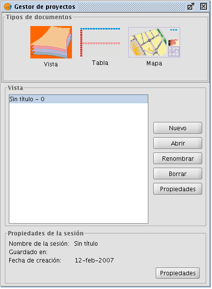
Figure 9: Project manager of gvSIG
After clicking on the Current projection button of the View properties dialog (see figure 10), the New CRS dialog will open (see figure 11) which has been described in the previous section.
IMPORTANT: Currently it is not possible to re-project an open view, so if you change the CRS while the view is open, the results may be erroneous.
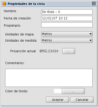
Figure 10: View properties dialog

Figure 11: Selection of the CRS
This section describes how to set the default CRS for every new View that is created in gvSIG.
The default CRS is defined in the Preferences window of gvSIG which can be accessed through the menu (Window->Preferences) or with the corresponding button in the toolbar  , see figure 1.
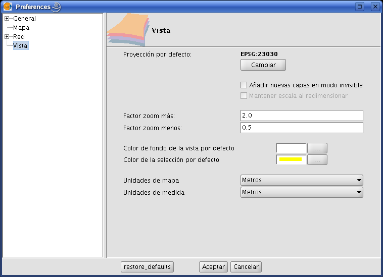
Figure 1: View Preferences
When clicking on the Change button, the New CRS dialog is displayed which lets you select the default CRS, see figure 2.
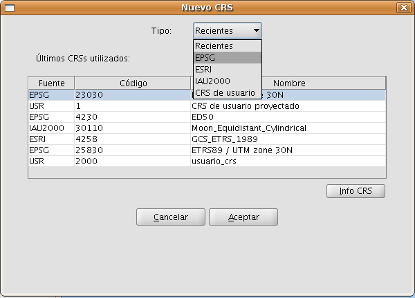
Figure 2: Select CRS. Recent CRS
In this dialog you can select CRS from five different repositories:
- Recent: This includes the CRS that have been used previously (Figure 2). The list of recent CRS will be available in the current and future executions of gvSIG and is not linked to a specific project.
- EPSG: This lets you browse and select CRS from the EPSG (European Petroleum Survey Group) database.
- ESRI: This lets you browse and select CRS from the ESRI database
- IAU2000: This lets you browse and select CRS from the IAU2000 database.
- User CRS: With this option you can create or select a user-defined CRS. When creating a new user-defined CRS, you can base this CRS on existing CRS from the EPSG database or create it from scratch.
Below, a brief description of each option is presented.
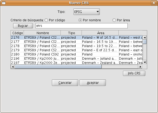
Figure 3: EPSG repository
The selection of CRS from the EPSG database can be done through three search criteria: through the EPSG code (for example 4230), through the name of the CRS (for example ETRS89), or by the area where the CRS is used (for example Spain). The two last cases are character string searches, resulting in those CRS where the name or area description includes the introduced string.
By clicking on the Info CRS button, you can access detailed information about the CRS that is selected in the table at the moment when you click the button, see figure 4 and 5:
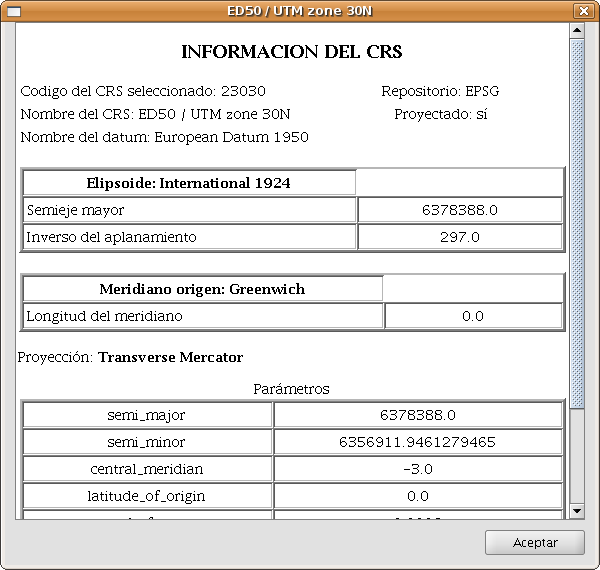
Figure 4: Information of the selected CRS
In the information that is shown for the selected CRS, it is important to note the Proj4 string (at the bottom). The jCRS library includes CRS operations through the Proj4 library (link), where the results will be correct if this string has been correctly constructed. This information could be useful for advanced users.
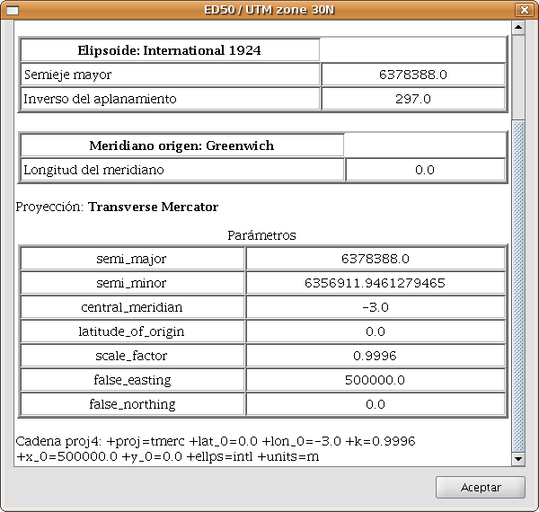
Figure 5: Information of the selected CRS, including the proj4 string
This information sheet for selected CRS is available for all repositories included in the extension.
The selection of CRS from the IAU2000 and ESRI databases, (see figure 6 and 7, respectively) can be done by searching on the CRS code or name of the CRS.
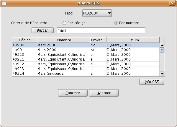
Figure 6: IAU2000 repository
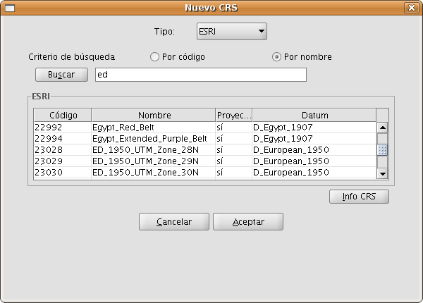
Figure 7: ESRI repository
The User CRS dialog allows for the management of the user database including select, edit or delete existing CRS, or create new CRS.
The selection of existing user-defined CRS (see figure 8) can be done by searching on the CRS code or the name of the CRS. Since there are normally only a few user-defined CRS, all user-defined CRS will appear in the table by default when the New CRS dialog is opened or when a search is performed without any code or search string.
The process of creating, editing and deleting of user-defined CRS will be explained in a later section of this manual.

Figure 8: Repository of user-defined CRS
In accordance with ISO 19111, there are two types of operations to relate two different CRS: conversion operations and transformation operations:
- Conversion of coordinates is used when the datum of the CRS of the layer coincides with the datum of the CRS in the view, in other words, both CRS correspond to the same geodetic reference system but are in different coordinate systems. If you choose the CRS of the layer in this case you need to select the option No transformation.
- Transformation is used when the datum of the CRS of the layer does not coincide with the datum of the CRS of the view. In this case there are two types of coordinate operations:
- The operation involves only a transformation when the coordinate system of the CRS of the layer coincides with the coordinate system of the view; in both CRS the positions are expressed in the same coordinate system but in a different datum.
- The operation involves a transformation and a coordinate conversion when both the datum and the coordinate system of the CRS of the layer and the CRS of the view are different.
If a transformation is needed, you must choose the type of transformation for the layer in the CRS selection dialog (see Figure 20) and click the Next button to continue to the corresponding transformation dialog.
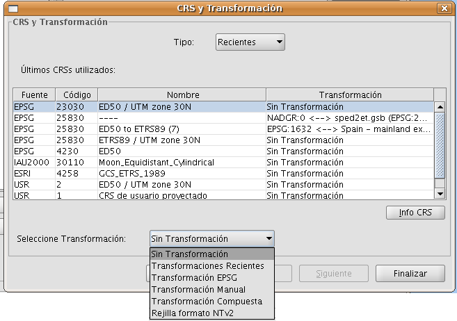
Figure 20: Select the type of transformation
The transformation dialog depends on the type of transformation to be performed:
- EPSG transformation. These are the official 7-parameter transformations as defined in the EPSG repository. The dialog for this type of transformation shows a table where all the applicable EPSG transformations are listed, with the CRS that was chosen for the layer as source CRS, and the CRS of the View as destination CRS (see Figure 21).
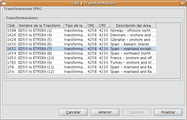
Figure 21: Transformación EPSG
Keep in mind that the transformation operations of this type are always between the base CRS (i.e. non-projected CRS), and therefore if the CRS of the view or the CRS of the layer is projected, the corresponding base CRS will appear in the fields Source CRS and Destination CRS. Keep also in mind that for this type of transformation, the CRS for the View and the CRS for the layer must come from the same EPSG repository. If they come from different repositories, the table will appear empty.
- Manual transformation. With this option you can define a Helmert transformation through the introduction of the 7 parameters (see Figure 22).
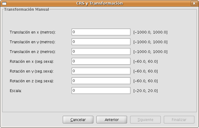
Figure 22: Manual transformation
- Grid based transformation (see Figure 23). With this option a transformation based on an NTv2 grid file is applied. For this, you must choose the NTv2 file from a list of available files or import it from a location to be specified. Since in the NTv2 file the translations have been calculated in a given base CRS, you must indicate here whether the NTv2 was calculated in the base CRS of the View, or the base CRS of the layer.
IMPORTANT: The grid file has a specific scope, which can be deduced from the file information that is displayed in the processing panel. Transformation is not applied beyond this scope, so the re-projection accuracy will be considerably lower, since only the corresponding coordinate system conversion would be applied.
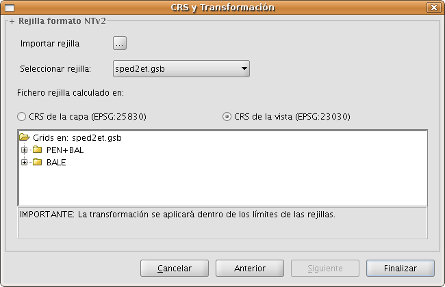
Figure 23: Grid based transformation
Recent transformations (see Figure 24). With this option, you can select a transformation that has been used before. The list of recent transformations will be available in the current and future executions of gvSIG and is not linked to any specific project.
There are two ways to select a recent transformation. The first way is through the CRS selection panel for the layer. There is now an additional field in the table to indicate if the selected CRS has been used together with a transformation in any recent execution of the program. If you select the CRS and recent transformation, you can do two things:
- Accept the CRS and transformation.
- Continue the process of selecting the transformation. This will be helpful to review the selected transformation, because in the next panels the information of the selected transformation will be loaded, so that you can still change it or select another transformation, in which case in the next CRS selection for the layer, a new recent transformation will be added with the chosen settings. To access the information of the CRS and the transformation, just click on the Info CRS button (see Figure 25).
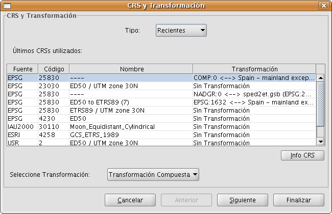
Figure 24: Selection of the CRS for the layer and recent transformation
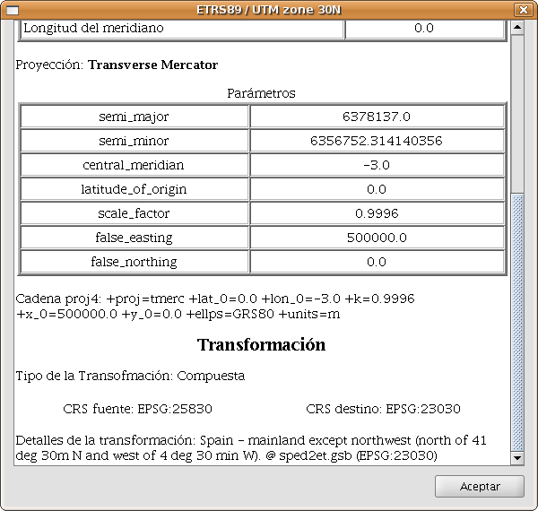
Figure 25: Information of the CRS for the layer and the selected transformation
The second way to select a recent transformation is through the selection of CRS without transformation and then select Recent transformations as the type of transformation, after which a panel is displayed where you can choose from transformations that were previously defined (see Figure 26).
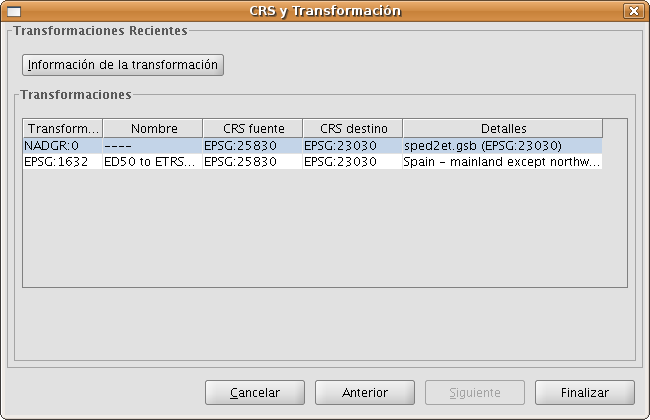
Figure 26: Recent transformations
Composite transformation. This type of transformation is new for this version. The objective of composite transformations is to provide gvSIG users with the possibility to represent two CRS with different datums without the transformation between those two CRS, but with a transformation of those two CRS into a third CRS.
The composite transformation can play an important role when you need to define two transformations, one that refers to the CRS of the layer and the other to the CRS that has been defined for the view.
With this mechanism, you can set the CRS for the layer and the CRS of the View through an intermediate CRS that connects the two CRS.
To do this, after selecting the CRS of the layer and setting the type of transformation to Compound transformation, you need to:
- Define the transformation to be applied to the CRS of the layer (Figure 27)
- Define the transformation to be applied to the CRS of the view (Figure 28).
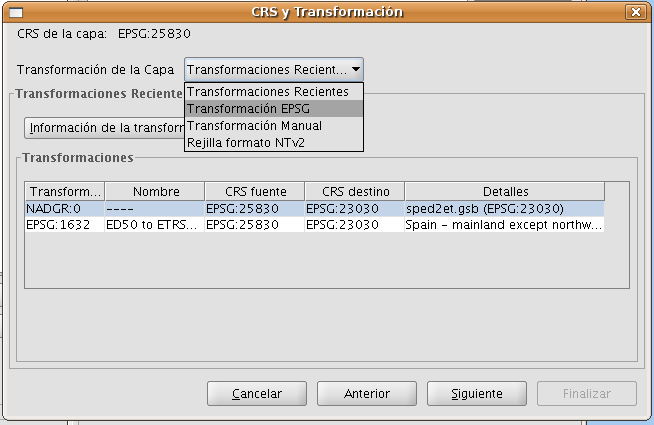
Figure 27: Select the transformation for the CRS of the layer

Figure 28: Select the transformation for the CRS of the view


